Final Project -DEV
This document is under Construction
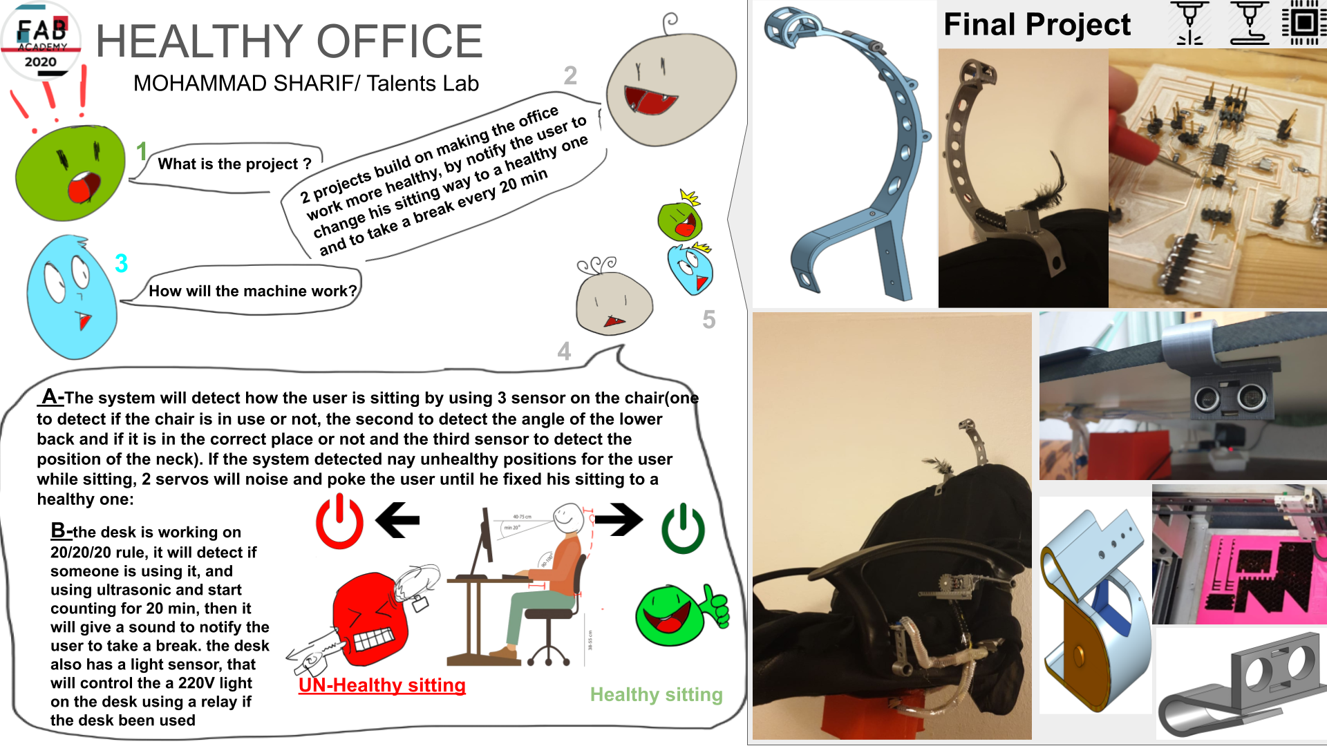
Hello, maybe for the last time, I am greeting you..... but the future is ahead for all of us , all the best >_<
let's talk about back pain, nick pain.... do you set for many hours in fromt of your screen, workin in your desk in your office?
Same for me....... but I am in a different level , I belive that I have meansuned bfor, in application and Implications week befor, but one more time will :
for example, check this comic from Cassandra Comics

I am even worst that that!
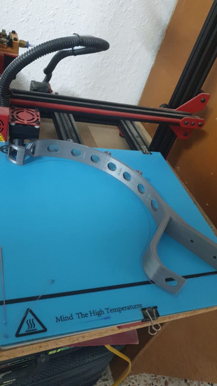
now, the chaire that I am using does not have a anything to support the neck, just like the cahir in the comic, for that, I have dsigned the first draft for the final design, in the design, I linked bothe arms of the chair with the new neck support, check the dsign here:
in this design, the screw that support tha hands of the cahre will carry the new parts that connect the new neck part off the chair
then I remembered that I have a supper power called"super speed sleep_just by Lay the head"... this will help me sleep very fast, and it readly happens from time to time.... and I wanter my work desk to be productive, so the firt design is canceled...
after that, I cahnged the design to a sensor based position that place every sensor in the neece position to detect the way of healthy sitting, by placein a sensor with 3D printed parts in neck, back and sitting position of the chair, check the first video for the neck design:
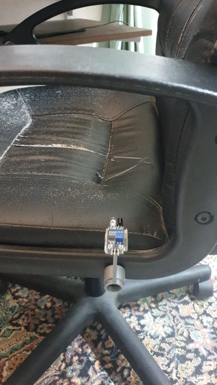
then designed the 3D design for the side sensor, by placing it with the same screws that holde the hands of the chair:
now, let's set the 3D printed parts, first with the side mount sensor :
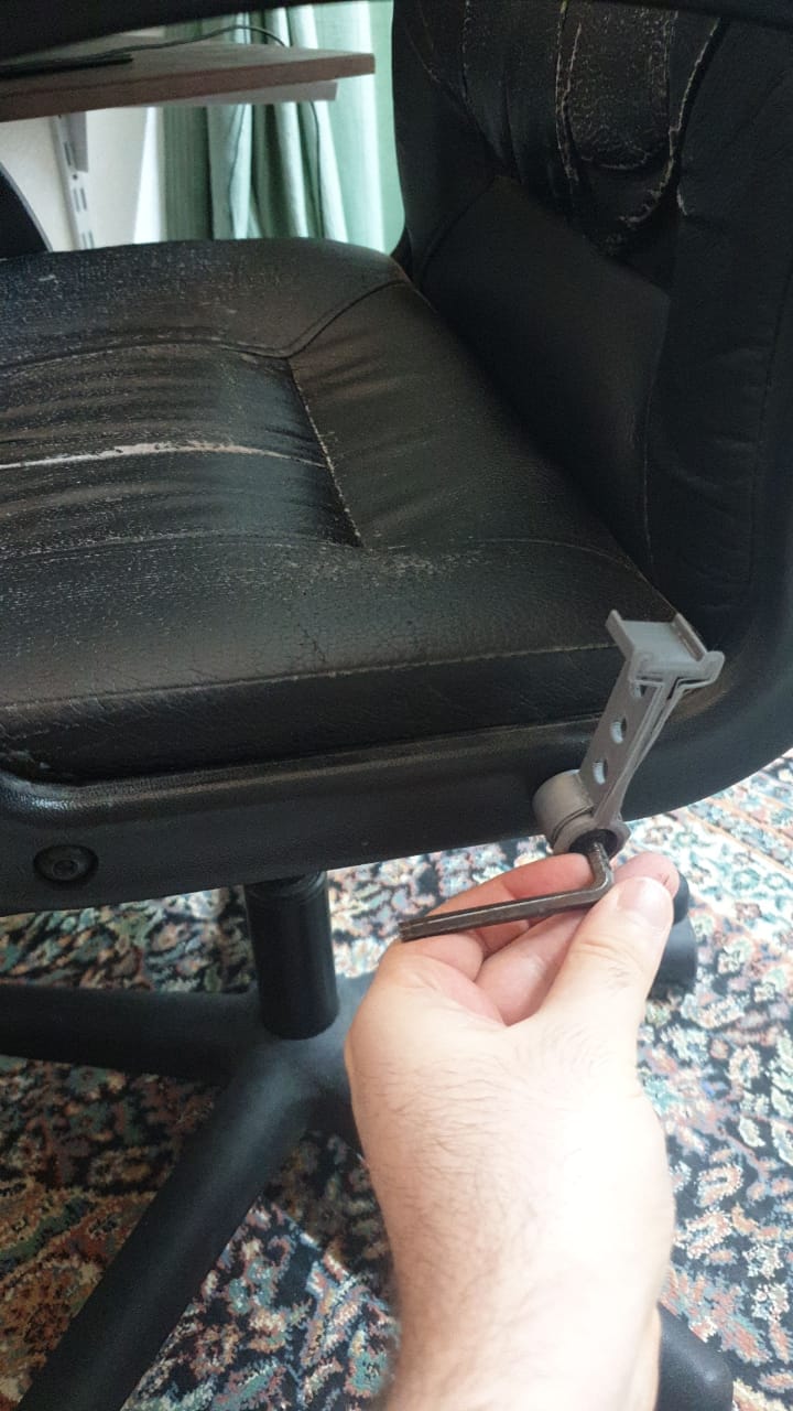
then, place the ir proximety sensor on it:
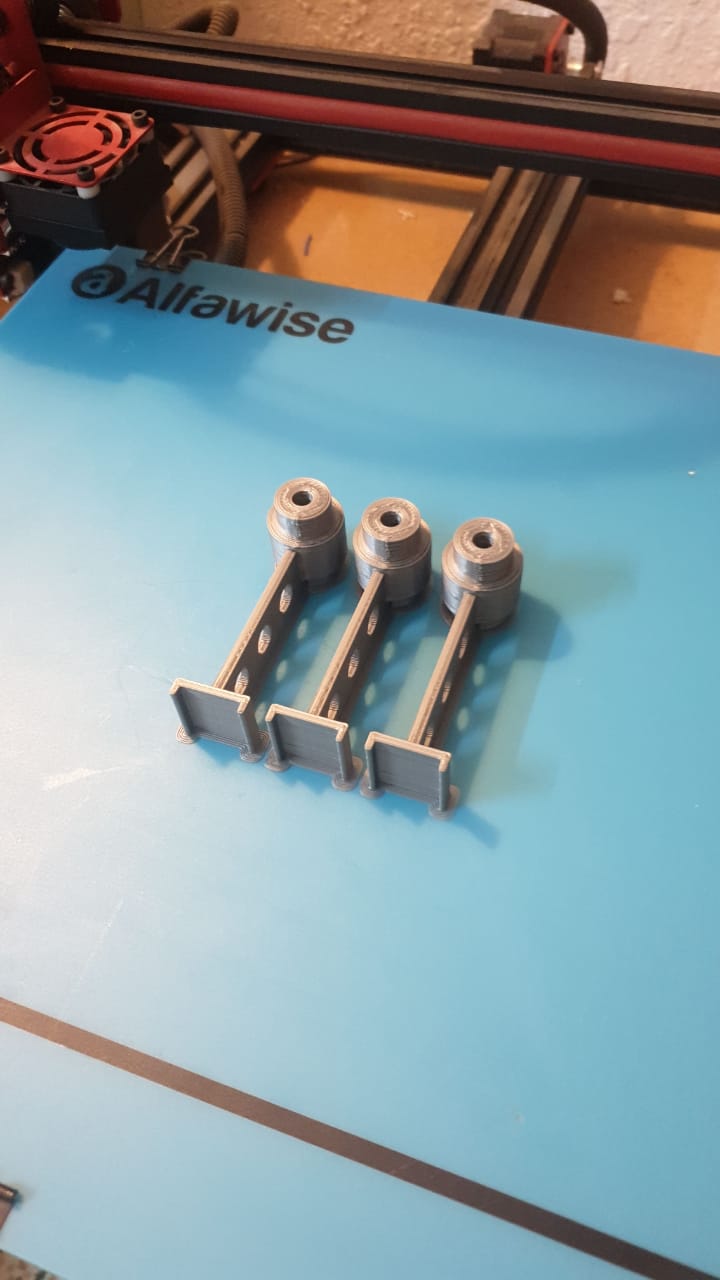
print more of the side mount sensors , can be used to add more sensors to the chair:
now let, palce the 3D printed senser part "neck part", ofcource, this part has been designed in 2 ways, after testing the first part "bule color" which did not work well"it need double side tabe to be paced on the chair", and update it the new design "silver color" that can be placed on the chair and it will no move:
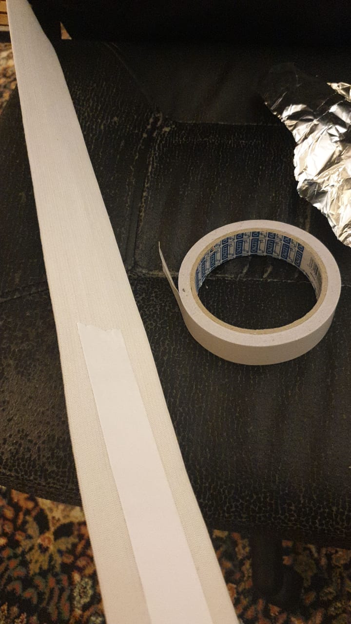
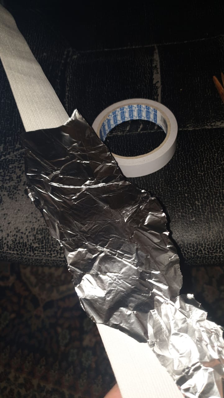
now, add the Stretchable part that wii be used as the sensor of the lower back position on the chair:
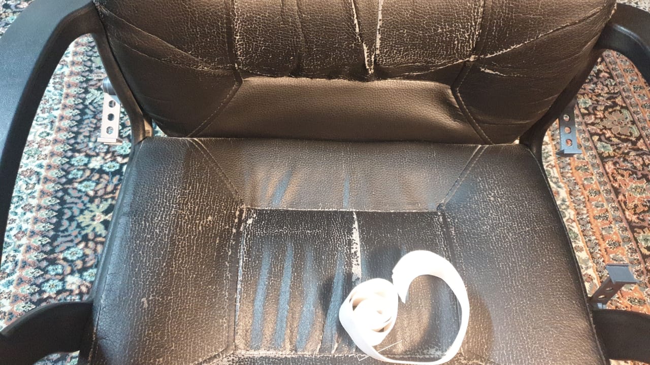
this part is Inspired by MAKEY MAKEY , by coonecting the circuit or disconnect it using tin:
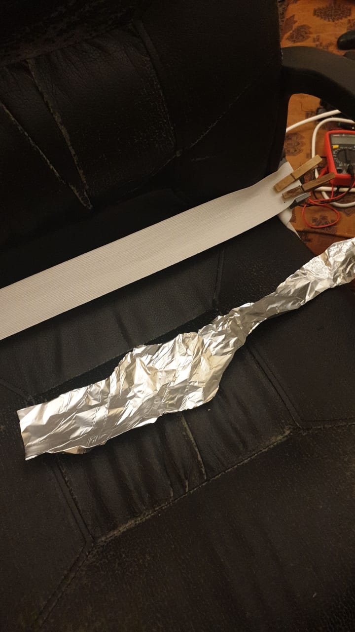
first try was by Adhesive double side tape to the tin
same for the back of the chair:
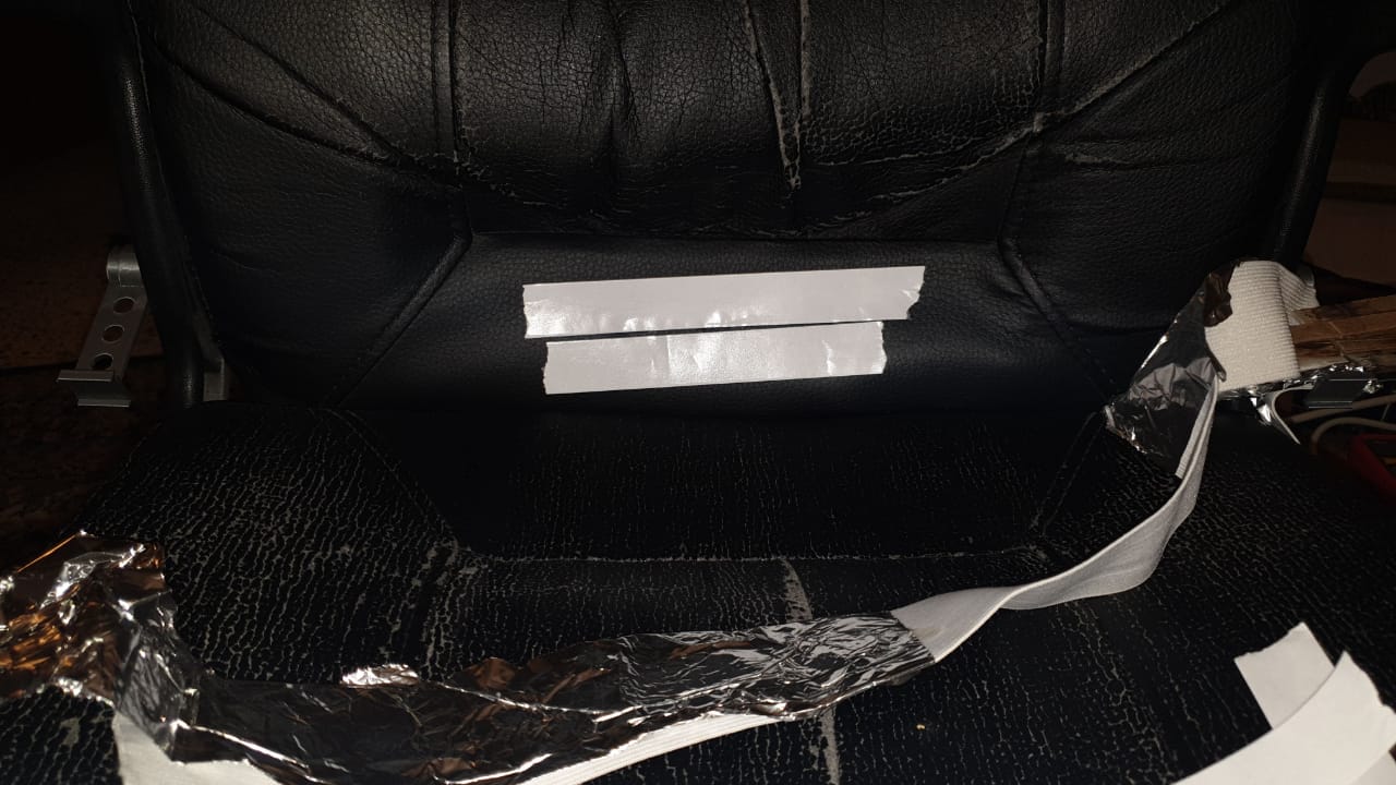
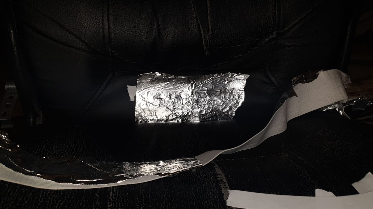
but I have faced some probles when striching the it, so I Sew it together, with some free spaces to be starchable without Separates the tin from it:

then I added a clip to both side of the Stretch sensor:
you can see the design of the clip here
:how about we go step by step for the designs:
for the head sensor: I started with the side skitch:
extruded it for 30 mm:
added some holes for future upgradability
added some holes so I could add a sensor on the top:
and for future upgrades, I added a plugins to it , so if want to add something to it in the futre, this will help to:
now, let's look at the desk pcb case:
I have used the clips design, you will see it soon below,then adde the skitch that will hold the pcb and boards:
extrude it , then added a side wall to it:
then adde this to plug it to it's external case:
external case for the desk pcb:
for cable managment, I designed this holder:
extruded it for 20 mm:
then cutted it to make it more flexable:
there is sizes for it , 15mm and 18 mm:
now for the case of the chair pcb, first the base and the external case skitch:
after extruding it, I added and extruded the part that will hold the pcb at place:
added a hoel and holder for cable managment, and cut it to be more flexable:
then added some holders with holdes to connect it to the external case:
external case with extruded parts to hold the pcb base:
now, let's go to the top servo case, a simple one and will do the job:
extrude the skitch for it main sizes that will fit the neck servo:
then cut the part wher the shaft of the servo will come out from:
now let's take a look at the side sensor and servo holder:
make a cylender, so the screws of the side of the chair that hold the handels can be used to hold the 3D printed parts as well:
then make the elig that will carry yht sensor :
and add a place for the sensor to placed on:
add add some holes for future upgrades:
same for the side servomotor holder:
back to the desk, ultrasonic holder:
first, lets draw the clips"used in a previous 3D design above":
add extention to it and add holes, for future upgrades:
then add the sketch for the face of the ultrasonic,and extrude it:
relocate it:
for the servo gears; I used inkscape using extentions, render, gear theen used gear tool and rack gear tool to make them both:
then extruded them and printed them....
you can check the 3D printed design here:
for the head sensor: HERE
for the base of chair pcb: HERE
for the base of cable mangment: HERE
for the base of clips: HERE
for the base of deskcase pcb: HERE
for the base of neckservo: HERE
for the base of sidemotor: HERE
for the base of side motor mount: HERE
for the base of sidesensor: HERE
for the base of ultasonic desk mount: HERE
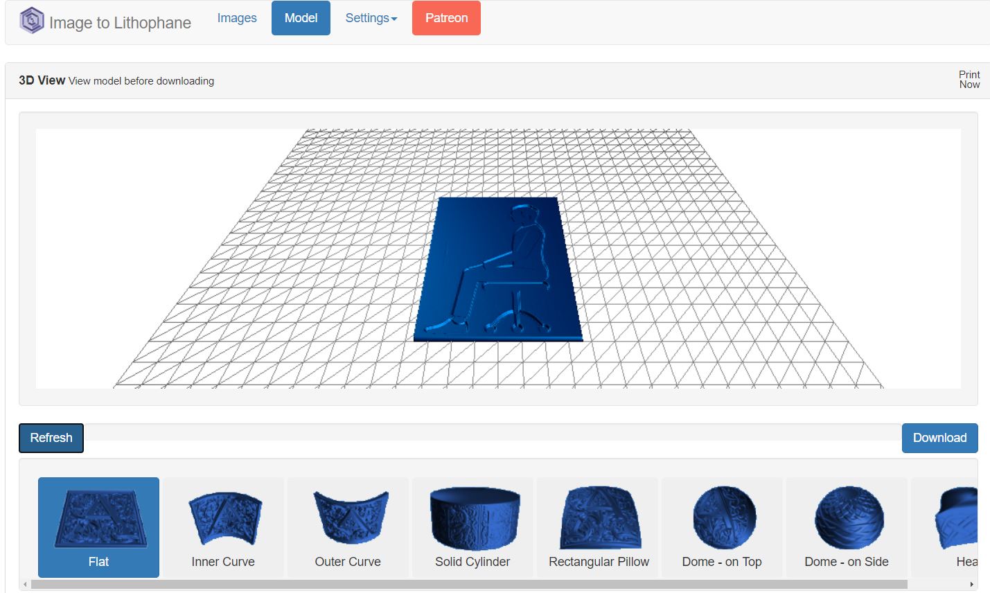
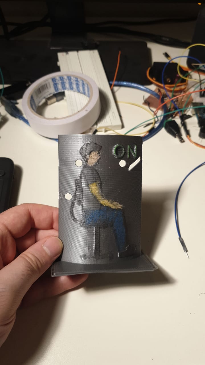
then, lets print the panel that will notefy the user if he is not sitting in the correct way:
I am using a methode called lithophanes to convert a sitting picture to a 3D printable model, you can use this link to make it.
using some colors, it is more clear now:
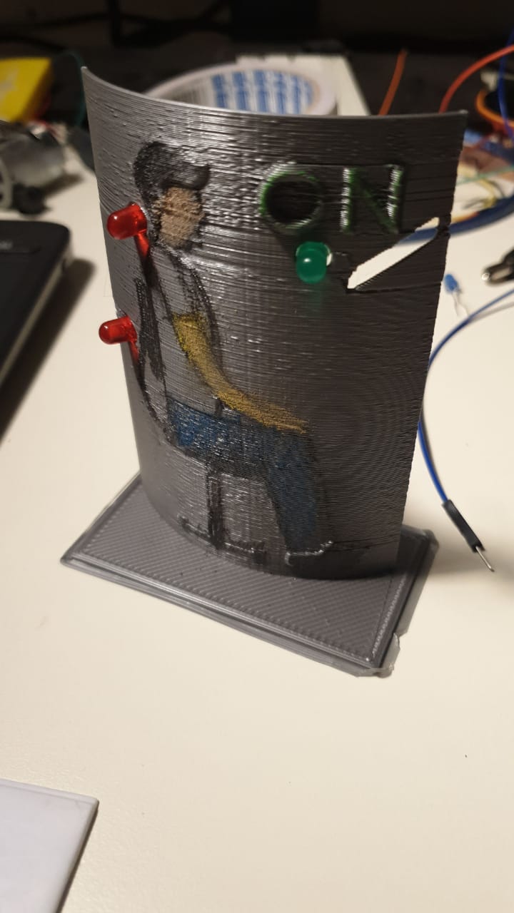
add some leds to show the case of the sitting:
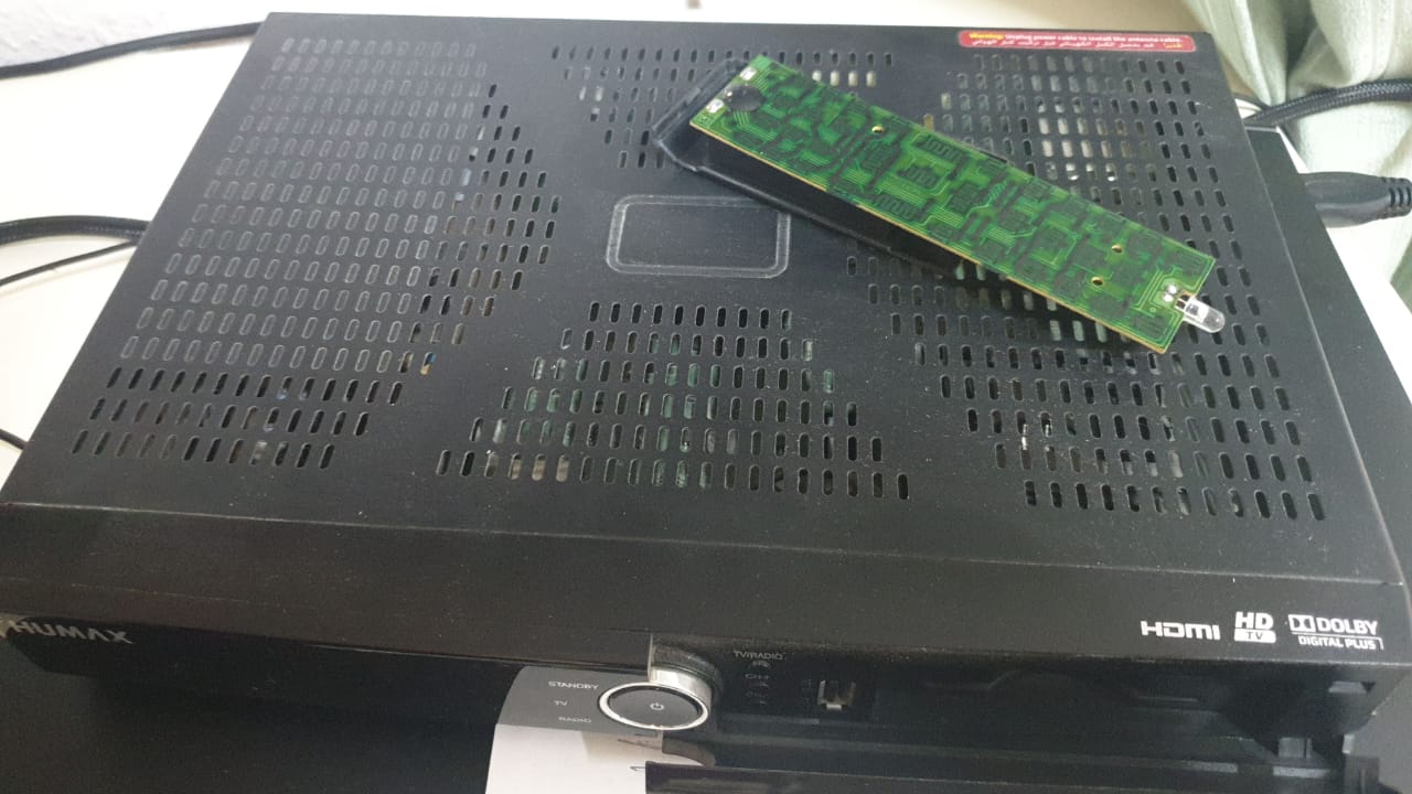
NOW, I am facing a problem, how to send the signal between the arduino"controller" on the chair to the controller on the desk to show the use the way he is sitting?
I have many ways, but all need to buy soem parts online, and online shoping now is taking a lot of time to delever thies days, so I thought of something evil! "or not".....
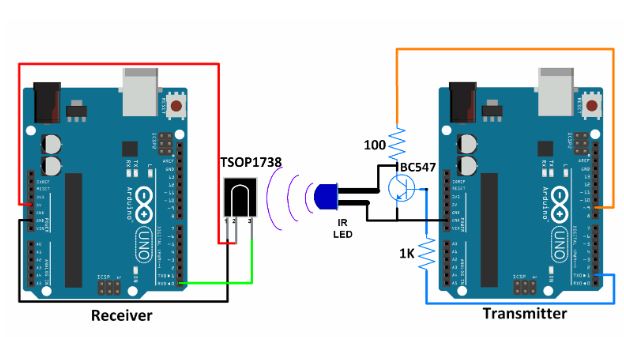
I will destry my old TV reciver and harvest the ir sender and resever from it to use it for connecting the 2 controllers
some photos for that Surger :
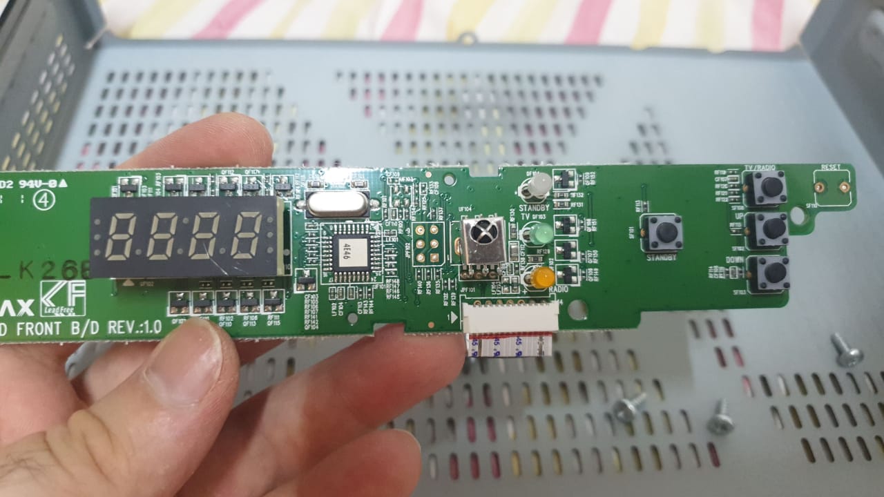

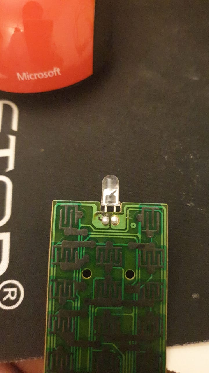
now, let's connect the ir sender and reciver and take the date from it :
I am using this code to read the signal of the IR:
#includeconst int RECV_PIN = 11; IRrecv irrecv(RECV_PIN); decode_results results; void setup(){ Serial.begin(9600); irrecv.enableIRIn(); irrecv.blink13(true); } void loop(){ if (irrecv.decode(&results)){ Serial.println(results.value, HEX); irrecv.resume(); } }
the signal that is sent is Encrypted to the following :
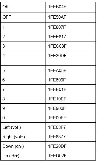
so , if "OK" is pressed on the remote control, the ir reciver will read 1FEB04F signal...
OFF button on the remote controller will be readed as 1FE50AF in the ir reciver... and sooooo on....
now, let's connect the ir reciver and sender to the 2 controllers, see the connection below:
the system of the project should work like this:
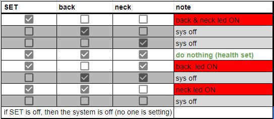
the system will work if the "set" snesor is on (when someone is sitting on the chair), then it will reads the condition of the other 2 sensors (back and neck sensors), depends on them, the signal will be sent to the contorller on the dest to send " show , light on or of leds" notification to the user
full code is still WORK IN PROGRESS, but you can take a look at the prototyp codes for bothe the sender and reciver controllers:
sender arduino code:
  #define cr_pin 9      //for  IR pin communication

  int setsensor = 2;    // variable for reading the pin status
  int setval = 0;
  int backsensor = 3;
  int backval = 0;
  int necksensor = 4;
  int neckval = 0; // variable for reading the pin status

  void setup() {
    Serial.begin(1200);  /* Define baud rate for serial communication */
    tone(cr_pin, 38000);  /* For modulation at 38kHz */
    pinMode(setsensor, INPUT);    // declare pushbutton as input
  pinMode(backsensor, INPUT);
  pinMode(necksensor, INPUT);
  }

  void loop() {
    if( digitalRead(setsensor)==HIGH)   // read input value


    {
      setval=1;
      Serial.println(setval);
      delay(1000);
    }
    else
    {
      setval=2;
      Serial.println(setval);
      delay(100);
      }
  //--------------------------

  if( digitalRead(backsensor)==HIGH)   // read input value


    {
      backval=3;
      Serial.println(backval);
      delay(1000);
    }
    else
    {
      backval=4;
      Serial.println(backval);
      delay(100);
      }


      //------------------------

      if( digitalRead(necksensor)==HIGH)   // read input value


    {
      neckval=5;
      Serial.println(neckval);
      delay(1000);
    }
    else
    {
      neckval=6;
      Serial.println(neckval);
      delay(100);
      }
  }
reciver arduino code:
  int neckled = 9;
char data = 0;            //Variable for storing received data
int inByte =0;

void setup() {
  Serial.begin(1200);  /* Define baud rate for serial communication */
   pinMode(neckled, OUTPUT);

}


void loop() {

if (Serial.available())

{

int state = Serial.parseInt();

if (state == 5)

{

digitalWrite(9, HIGH);

Serial.println("Command completed LED turned ON");

}

if (state == 0)

{

digitalWrite(9, LOW);

Serial.println("Command completed LED turned OFF");

}

}

}
let's take a lock to the implementation and how the setup is working for the project, check the follwoing video to understand:
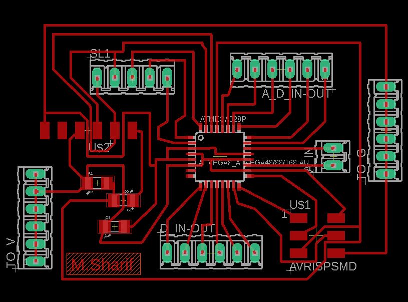
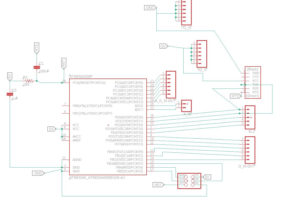
the design of the PCB is ready, just waiting for the lab to open, check the design below:
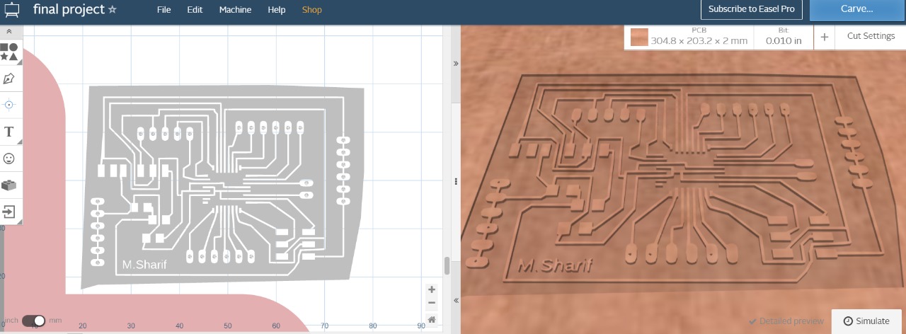
take a look at the eagle degin :
----OFFFFFFFFFFFFFFFFFFFFFFFFFFFFFFFFFFFFFFFFFFFFFFFFFFFFafter thinking about my project, using 2 atmega for it is a waist.. so I will use 2 attiny 44 for it.
also, first, lets try the code for communication between the 2 pcbs using ir signal:
first is the code of the sender attiny 44:
  //sender 9 L------ V1

  #include<}SoftwareSerial.h>// serial library
  SoftwareSerial mySerial(1, 0);
  void setup() {
    mySerial.begin(9600);  /* Define baud rate for serial communication */

  }

  void loop() {
    int count;
    for(count = 0; count<}2; count++)
    {
       digitalWrite(7,HIGH);
    delay(50);
      mySerial.println(count);
        delay(8);
       digitalWrite(7,LOW);
    delay(20);
      delay(100);
    }
  }
this code will send 2 numbers (0 and 1) using the rx pins in the sender attiny44
then we have the reciver code that will turn the build in led for long time, or blink for 2 times depends on the signal recived from the sender:
  #include<}SoftwareSerial.h>// serial library
  SoftwareSerial mySerial(1, 0); // define the serial and the TX=1 and RX=0

  char ON = '1';
  char OFF = '0';


  void setup() {
     mySerial.begin(9600);  /* Define baud rate for serial communication */
  pinMode(7,OUTPUT);
  }

  void loop() {
     char chr = mySerial.read();
  if (chr ==  ON) {// if the chr have the same value of ON, the LED will be ON.
      digitalWrite(7, HIGH);
      delay(100);
    }
     if (chr ==  OFF) {
       digitalWrite(7,HIGH);
                delay(10);
                digitalWrite(7,LOW);
  delay(10);
  digitalWrite(7,HIGH);
                delay(10);
                digitalWrite(7,LOW);
  delay(10);

    }
     else {

         digitalWrite(7,LOW);

  }
  }
check video to see how it works:
all is working and everyone is happy...............That what they lie to you......after testing in arduino the ir segnal was able to travel for 1.5meter without problem, I was naive...and happy for it
and I have made a ciruit in eagle for the ir :
check eagle file HERE
and HERE
and after testing it with attiny, it did work, but unfortunately it did not have the same range.... at maximum it went for 10 to 15 cm. and that range will not work with the idea of my project.....after all that time, it did not work.....>_< SAD
good to learn and test , learned in the hard way....
Waht does not kill you.... make you sadder and wiser
and for that, I will build the project from the groud up using a completely separated 2 system build on attinys 44 or 84
check eagle file HERE
and HERE
let's talk about the new system that I will build for the chair:
what about the sensors that will detect the healthy setting position?
and how the user, me, will know if he is setting correctly or wrong?
you may ask...why?.... the answer is simple:
why using this methode? first, let's whatch this video:
the channel is "Simone Giertz"on youtube, go check it for more projects....anyway, the idea if , you can set your phone alarm to wake you up, but this may not be the most relaiable way to be 10000% sure that you will ake up form the first time.....
THis is the same idea for my project, only adding some sound or light notification for you to set in a healthy way may not be good Enough TO REALY CHANGE THE WAY YOU SET. and for that, I am using a direct body connectsion to make you for real change the way you set .... or the noise will keep on coming for you and the poking will never stop
now let's talk about the other side of the project, the table, or to be more exact, the removable talbe that I have built:
this table has multi shelves ability; you can add multible liyers and Shelves or remove them from the wall:
it is built on a shelf holder :
and you can add as many shelfs as you want by adding a holder to them:
and adding a light to it, this will be used in the project as will for auto ligh system depends on the condition:
all of this was build of the reason of making the best use of the space in m room, specilly in the Quarantine... you need to stay at home and do fill your time in something"if all U do is fabacademy...you may do some braindamage from all the thinking....don't tell MR. neilg---- you need to do some sports"so I did some kickboxing in my room"I am noob and still playing around":
so when I want to do some kickboxing, all i need to free some space in my room is taking of the desk and store it under my bed
NOW, let's talk technical about the desk:I ahve build a system that will detect if I am using the desk or not, and help my to lower the stress from long work hours and lower the use of the electricity by controlling the light in the desk:
see this video for 20/20/20 rule:
test for the desk pcb with 20/20/20 rule :
test for the desk pcb after adding it to the desk :
test for the chair pcb :
and after all that work, let's take a look at the final project selfie video that I have taking...hope you like it, and explained more for you:
PROJECT LIVE VIDEO:
and heer is the code of the chair pcb:
  int ledPin = 0; // choose the pin for the LED
  int neck = 5;   //neck sensor
  int inPin = 2;   // lowerback pushbutton pin
  int val ;     // set detecter
  int setlow;  //lowerback lowerback pushbutton --condition
  int y;
  int x;
  int buzz = 4;
  //int sound;
  int head;

  void setup() {
    pinMode(ledPin, OUTPUT);  // declare LED as output
    pinMode(2, INPUT);    // declare pushbutton as input
      pinMode(8, OUTPUT);
    pinMode(3, INPUT);
    pinMode(7, OUTPUT);
     pinMode(neck, INPUT);
      pinMode(buzz, OUTPUT);
  }

  void loop(){
  val = 0;


    val = digitalRead(3);  // if sitting
  setlow=digitalRead(2);
    head=digitalRead(5);

    //-----------------------------------------------------


    if(val ==LOW){
  //if person is setting ---------------------------------
  digitalWrite(buzz, HIGH);
  delay(1);
  digitalWrite(buzz, LOW);
  delay(10);
  digitalWrite(buzz, HIGH);
  delay(1);
  digitalWrite(buzz, LOW);
  delay(30);
  digitalWrite(buzz, HIGH);
  delay(1);
  digitalWrite(buzz, LOW);
  delay(50);


    if ((setlow == HIGH) && (head ==HIGH)) // un healthe set(both neck and back)
    {         // check if the input is HIGH (button released)
   digitalWrite(ledPin, HIGH);  // turn LED OFF
  for ( x = 10; x <= 30; x++) {
      analogWrite(8, x);
      delay(10);
     analogWrite(7, 1);

    }
    }

   if ((setlow == HIGH) && (head ==LOW))
  {
  for ( x = 10; x <= 30; x++) {
      analogWrite(8, x);
      delay(10);

      //digitalWrite(ledPin, LOW);  // turn LED ON
    //  for ( x = 10; x >= 9; x--) {
     // analogWrite(8, x);
      delay(10);
         analogWrite(7, 0);
  digitalWrite(ledPin, HIGH);
   delay(1);
      digitalWrite(ledPin, LOW);
   delay(1);
   digitalWrite(ledPin, HIGH);
   delay(1);
      digitalWrite(ledPin, LOW);
   delay(1);
    }

        }


     if ((setlow == LOW) && (head ==HIGH))
     {
     analogWrite(7, 1);
     delay(50);
     analogWrite(7, 0);
     }


    }

    else
    {
    digitalWrite(buzz, HIGH);
  delay(20);
  digitalWrite(buzz, LOW);
   analogWrite(7, 0);
    }


    delay(100);
  //digitalWrite(8,1);
  //delay(50);
  //digitalWrite(8,0);
    }

    //if (val == LOW){
     // digitalWrite(ledPin, LOW);  // turn LED ON
     // analogWrite(8,0);
the connection to the chair pcp are the following:
and the code for the desk:
                     const int trigPin = 0;  // defines pins numbers
                     const int echoPin = 1;  // defines pins numbers


                     int L ;
                      int lights = 4;
                     int relay =5;
                     int buzzer = 6;
                     long duration;  // defines variables
                     int distance;   // defines variables

                     int timez;

                     void setup()
                     {
                      pinMode(trigPin, OUTPUT); // Sets the trigPin as an Output
                      pinMode(echoPin, INPUT); // Sets the echoPin as an Input
                   pinMode(7, OUTPUT);
                     pinMode(relay, OUTPUT);
                      pinMode(buzzer, OUTPUT);
                      pinMode(lights,INPUT);
                   timez=0;
                     }


                    void loop()
                    {
    startloop:


  L= digitalRead(lights);
                     digitalWrite(trigPin, 0);// Clears the trigPin
                     delay(100);
                     digitalWrite(trigPin, 1);
                    delay(5); // Sets the trigPin on HIGH state for 5 micro seconds
                     digitalWrite(trigPin, 0);
                     duration = pulseIn(echoPin, 1); // Reads the echoPin, returns the sound wave travel time in microseconds
                     distance = duration * 0.34 / 2; // Calculating the distance
                    delay(3);
                if((L==0)&&(distance<10))
                      {
                         timez=timez+1;

                        digitalWrite(7, HIGH);
                  digitalWrite(buzzer, LOW);
  digitalWrite(relay,LOW);

     if(timez==2760)//1 min = 140 timez...........timez=2760 >>for 20 min
                   {digitalWrite(7,buzzer);
                   delay(10);
                   digitalWrite(7,buzzer);
                   delay(10);
                   digitalWrite(7,buzzer);
                   delay(10);
                   digitalWrite(7,buzzer);
                   delay(10);
                   digitalWrite(7,buzzer);
                   delay(10);
                   digitalWrite(7,buzzer);
                   delay(10);
                   digitalWrite(7,buzzer);
                   delay(10);
                   digitalWrite(7,buzzer);
                   delay(10);
                   digitalWrite(7,buzzer);
                   delay(10);
                   digitalWrite(7,buzzer);
                   delay(10);
                   digitalWrite(7,buzzer);
                   delay(10);
                   digitalWrite(7,buzzer);
                   delay(10);
                   timez=0;
                   goto startloop;
                   }

                      }

   else if((L==1)&&(distance<10))
                {

                digitalWrite(buzzer, HIGH);
                delay(1);
                digitalWrite(buzzer, LOW);
                 delay(500);

                  digitalWrite(relay,HIGH);//desk lamp
                  digitalWrite(7,LOW);//pcb led


                  // digitalWrite(13,LOW)
                  timez=timez+1;
                    if(timez==2760)//1 min=300
                   {digitalWrite(7,buzzer);
                   delay(10);
                   digitalWrite(7,buzzer);
                   delay(10);
                   digitalWrite(7,buzzer);
                   delay(10);
                   digitalWrite(7,buzzer);
                   delay(10);
                   digitalWrite(7,buzzer);
                   delay(10);
                   digitalWrite(7,buzzer);
                   delay(10);
                   digitalWrite(7,buzzer);
                   delay(10);
                   digitalWrite(7,buzzer);
                   delay(10);
                   digitalWrite(7,buzzer);
                   delay(10);
                   digitalWrite(7,buzzer);
                   delay(10);
                   digitalWrite(7,buzzer);
                   delay(10);
                   digitalWrite(7,buzzer);
                   delay(10);


                   timez=0;
                   goto startloop;
                   }
                }


                    else
                     {
                       digitalWrite(relay,LOW);
                      digitalWrite(7, LOW);
                       digitalWrite(buzzer, HIGH);
                       delay(10);
                        digitalWrite(buzzer, LOW);
                       delay(100);
                       digitalWrite(buzzer, HIGH);
                       delay(10);
                        digitalWrite(buzzer, LOW);
                       delay(200);
                       digitalWrite(buzzer, HIGH);
                       delay(10);
                        digitalWrite(buzzer, LOW);
                       delay(300);
                       timez=0;
                     }
                    delay(10);
                    }
the connection to the desk pcp are the following:
Now, let't talk about another idea that I have added to the design, specifically the head senosr:
one of the ideas for my proejct can be implemented to the chair and I can add the design that I want and make it look more to my liking.. the head sensor has a holder on the top that by using it, I can add a new sheet to the chair and make it look different
or it can be added on old chairs, to revive them and yous them with better look
so it could look like some old traditional chair like this:
or some pure black "newish" chair like this:
for finishing as will, I have adde a case for the neck servo:and add more cable mangment:
and added more caple mangment to all the cables for both side sensor, side servo and side lowerback sensor----- and wire them all to the controller under the chair:
mroe angles:
just to see how I added the pcb under the chair, I used took out 2 screws from the chair , then added a base, with a 4 cornecrs to hold the pcb:
then started connecting the pcb to the chair sensors and servos:
take a coser look at the system inside the box for the chair:
and here is a video explaining :
to say the truth, my heart did not allow me to take off all the connections betwenn the pcb and other components in the chair, this will add more work for lazy ME
keep it in maind that if you saw any arduino in the picturs when using atting, it is only used to power the attiny up wiht VCC and GND
and to make things more clear, "cuse the video is not showing much"... I am building the contorller for the chiar using the screws of the base, andd controlling the system using attiny84_ check the eagle fils mentioned above near the pcb designs, and from it, a newtowrk of wires are going all areound the chair to take singnals from 2 IR proximity sensot and a pushbutton like senros in the lower back+ the cables also goes to 2 servo motors to notify the user of the chair
and as mentioned befor, with cabel managment and adding a cse for the pcb, we got it clean :
-----------------now let's take a look at teh desk after adding more cable mangemnt and adding a case to it:
let's take a look at the part inside the controller box for the desk after taking the cover of it
I am using this design as a base for the controlling system for the desk, iwch can be addacehd to the lower shalf of the desk :
here without the red box:
so from the top side you will see the controlle (attiny44) and from the front side, there is a small breadboard for cable connection and lastly, from the left side, there is an ardino for power soursing the attiny44 with VCC and GNG
Now, let'change the design of the desk pcb, want to use some LASER cutting for building the case for it, and here is the steps of the design:
I am uisng onshape, and here is the side panel :
I will make 6 panel for to cut in the laser, so go with me in the steps.... after extruding the firts pannel, I made a copy of it:
desinging the front and the back panel, all panels will be connecting with teaths:
front and back panel:
then the top panel
and here is the final design:
the design can be added to the table lower shalf, and within it, I will install the new system
now, lets convert the 3D design to 2D :
check the file for PDF design HERE
then , I send the file to inkscape, to add the setting ,fill and strok setting, then send it to the the laser cutter program:
let's start cutting:
at first text, I ma using wood, then at the end, I will use acrylic
here is the first cut from woor:
tring to add it to the fablab desk, for testing....the desing is made for my desk sizes, so if you found in this page that it is not fitting ....wait and see how I will test it in my desk and it will fit perfictly
after that, I cutted more using acrylic, thne started building it:
and here how it looks in acrylic case from the back after taking the back cover:
from the top after taking top cover:
and after closing the case...as you can see, I added to the deasign 2 holes so the capels comming out from the pcb can be conencted to the sensor sand the led:
if you notecd befor, in the older pcb desing , I used a breadbourd to work with connections and blug the buzzer.....but now< I make a a second "new" pcb that has an attiny84, with the same connection to the pcb that I am using for the chair pcb,and for the connection, I am using thies pins :
for the code, since it will do the same as task, even after chaning the pcb, I only need to rewrite the pins to the new pcb connection:
the connection to the desk pcp are the following:
and here is the connection for the new pcb:
check the citruit:
and hre is the code for the new cirucit...I just cahnget the pins in the code from the old one:
                       const int trigPin = 1;  // defines pins numbers
                       const int echoPin = 7;  // defines pins numbers


                       int L ;
                        int lights = 8;
                       int relay =3;
                       int buzzer = 0;
                       long duration;  // defines variables
                       int distance;   // defines variables

                       int timez;

                       void setup()
                       {
                        pinMode(trigPin, OUTPUT); // Sets the trigPin as an Output
                        pinMode(echoPin, INPUT); // Sets the echoPin as an Input
                     pinMode(7, OUTPUT);
                       pinMode(relay, OUTPUT);
                        pinMode(buzzer, OUTPUT);
                        pinMode(lights,INPUT);
                     timez=0;
                       }


                      void loop()
                      {
      startloop:


    L= digitalRead(lights);
                       digitalWrite(trigPin, 0);// Clears the trigPin
                       delay(100);
                       digitalWrite(trigPin, 1);
                      delay(5); // Sets the trigPin on HIGH state for 5 micro seconds
                       digitalWrite(trigPin, 0);
                       duration = pulseIn(echoPin, 1); // Reads the echoPin, returns the sound wave travel time in microseconds
                       distance = duration * 0.34 / 2; // Calculating the distance
                      delay(3);
                  if((L==0)&&(distance<10))
                        {
                           timez=timez+1;

                          digitalWrite(7, HIGH);
                    digitalWrite(buzzer, LOW);
    digitalWrite(relay,LOW);

       if(timez==2760)//1 min = 140 timez...........timez=2760 >>for 20 min
                     {digitalWrite(7,buzzer);
                     delay(10);
                     digitalWrite(7,buzzer);
                     delay(10);
                     digitalWrite(7,buzzer);
                     delay(10);
                     digitalWrite(7,buzzer);
                     delay(10);
                     digitalWrite(7,buzzer);
                     delay(10);
                     digitalWrite(7,buzzer);
                     delay(10);
                     digitalWrite(7,buzzer);
                     delay(10);
                     digitalWrite(7,buzzer);
                     delay(10);
                     digitalWrite(7,buzzer);
                     delay(10);
                     digitalWrite(7,buzzer);
                     delay(10);
                     digitalWrite(7,buzzer);
                     delay(10);
                     digitalWrite(7,buzzer);
                     delay(10);
                     timez=0;
                     goto startloop;
                     }

                        }

     else if((L==1)&&(distance<10))
                  {

                  digitalWrite(buzzer, HIGH);
                  delay(1);
                  digitalWrite(buzzer, LOW);
                   delay(500);

                    digitalWrite(relay,HIGH);//desk lamp
                    digitalWrite(7,LOW);//pcb led


                    // digitalWrite(13,LOW)
                    timez=timez+1;
                      if(timez==2760)//1 min=300
                     {digitalWrite(7,buzzer);
                     delay(10);
                     digitalWrite(7,buzzer);
                     delay(10);
                     digitalWrite(7,buzzer);
                     delay(10);
                     digitalWrite(7,buzzer);
                     delay(10);
                     digitalWrite(7,buzzer);
                     delay(10);
                     digitalWrite(7,buzzer);
                     delay(10);
                     digitalWrite(7,buzzer);
                     delay(10);
                     digitalWrite(7,buzzer);
                     delay(10);
                     digitalWrite(7,buzzer);
                     delay(10);
                     digitalWrite(7,buzzer);
                     delay(10);
                     digitalWrite(7,buzzer);
                     delay(10);
                     digitalWrite(7,buzzer);
                     delay(10);


                     timez=0;
                     goto startloop;
                     }
                  }


                      else
                       {
                         digitalWrite(relay,LOW);
                        digitalWrite(7, LOW);
                         digitalWrite(buzzer, HIGH);
                         delay(10);
                          digitalWrite(buzzer, LOW);
                         delay(100);
                         digitalWrite(buzzer, HIGH);
                         delay(10);
                          digitalWrite(buzzer, LOW);
                         delay(200);
                         digitalWrite(buzzer, HIGH);
                         delay(10);
                          digitalWrite(buzzer, LOW);
                         delay(300);
                         timez=0;
                       }
                      delay(10);
                      }
and here a test for the new desk system:
now,after instaolling it inside the box and connecting it to the sensor, showed above , lets try and insert it to my desk , see if it will fit in position:
fit perfictly in place...now let's connect the system to from the ultrasonic to tthe realy and ldr module:
I lefted the right hole in the case open, so the build in pcb buzzer sound can come out from the case
NS WITH THAT, the desk and chiar systems are done, and you can sit and "NOT enjoy" your unhealthy sitting way anymore
here is the items that I bout to work on the academy and the final project:
Material |
Quantity |
Cost IN $ |
Where TO BUY? |
Fplywood 50X90X2 cm |
1 |
5 |
|
hpl plate 70X 120X2 cm |
1 |
14 |
Industrial workshops OR IKEA |
Wall upright 84 cm |
2 |
9 |
|
LCD 16x2 |
1 |
10 |
|
Push Buttons |
2 |
1 |
|
Potentiometer |
1 |
3 |
|
PCB Coper Board15mm x 15mm |
4 |
6 |
|
shelf carrier |
4 |
10 |
|
SMD Capacitors |
2 |
0.16 |
|
SMD Resistors |
4 |
0.4 |
|
USB Cable |
1 |
2 |
|
Hand tool (drill) |
1 |
60 |
|
office Chair |
1 |
50 |
|
arduino UNO |
1 |
8 |
|
Muscle sensor V3 |
1 |
35 |
|
Ultrasonic Sensor |
1 |
6 |
|
flex sensor |
1 |
22 |
|
Light Sensor – LDR |
1 |
2 |
|
IR Infrared Obstacle Avoidance Sensor |
2 |
10 |
|
PLA FILAMENT |
one roll ~700gr |
35 |
|
Jumper wire package |
80 wire (kit) |
8 |
|
relay |
2 |
10 |
|
LEDS |
KIT (will use up to 9 leds) |
1 |
|
Screws~3mm |
15 |
2 |
|
Acrylic sheet 50X30 |
5 |
5 |
Total cost = 326$ USD
normally I would buy the electronics parts from a chaina from a good source and much lower price, but KSA is not allowing any thing to come from Chaina...
for time managment, this cycle of the academy was kind of crazy, some time we could go to the lab, some time we wnnd to stay home and image working on the machine,,,,or something, and for that, I went with this schedule:
-design the main physical parts of the project : MAY 20 >> MAY 31
-build the table MAY 5 >> MAY 9
-build the physical parts using the tools in the lab and my 3D printer in my house : JUNE 1 >> JUNE 20
-desing the pcb + coding and testing the system : JUNE 1 >> July 20
- woking on the fianl project video and presentaion and finish the missing parts of the previous weeks : July 21 >> July 31
-try to stay home and stay safe : the second half of the entire academy
PROJECT MANAGEMENT:
I am using app.ganttpro.com to build my project plan, go check them online.
Final presentation Video:
Final Poster PNG: